
🕔 Estimated reading time: 5 minutes
Comparison, specifications, and a comparison of the quantum field effect transistor (QFET) to the quantum coupled transistor (QCT)
Part I. Comparative Framework: QCT vs. QFET
- Conduction Mechanisms
- Coupling Types
- Material Stacks
- Operating Regimes
- Functional Behavior
- Conceptual Shift
→ Amplifying Evanescent Fields
(a) Recovering Lost Information
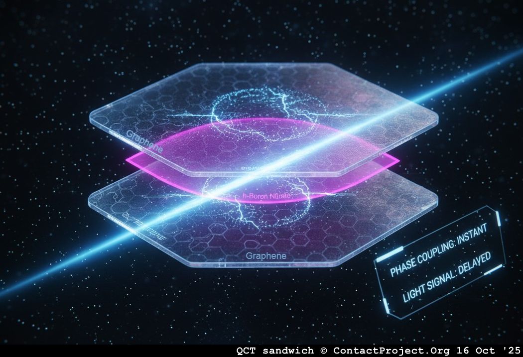
(b) Enabling Phase-Coupled Communication
(c) Accessing Hidden Quantum Channels
1. Conduction Mechanism
A Quantum Field-Effect Transistor (QFET) modulates the potential in a quantum well or two-dimensional electron gas (2DEG) channel through an electric field. Conduction still occurs through a continuous semiconductor layer such as GaAs, InP, or MoS₂.
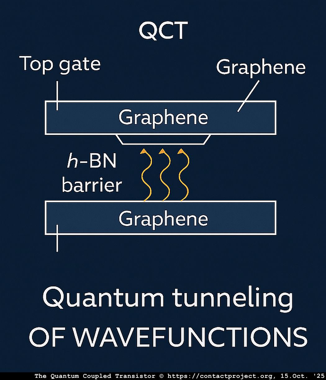
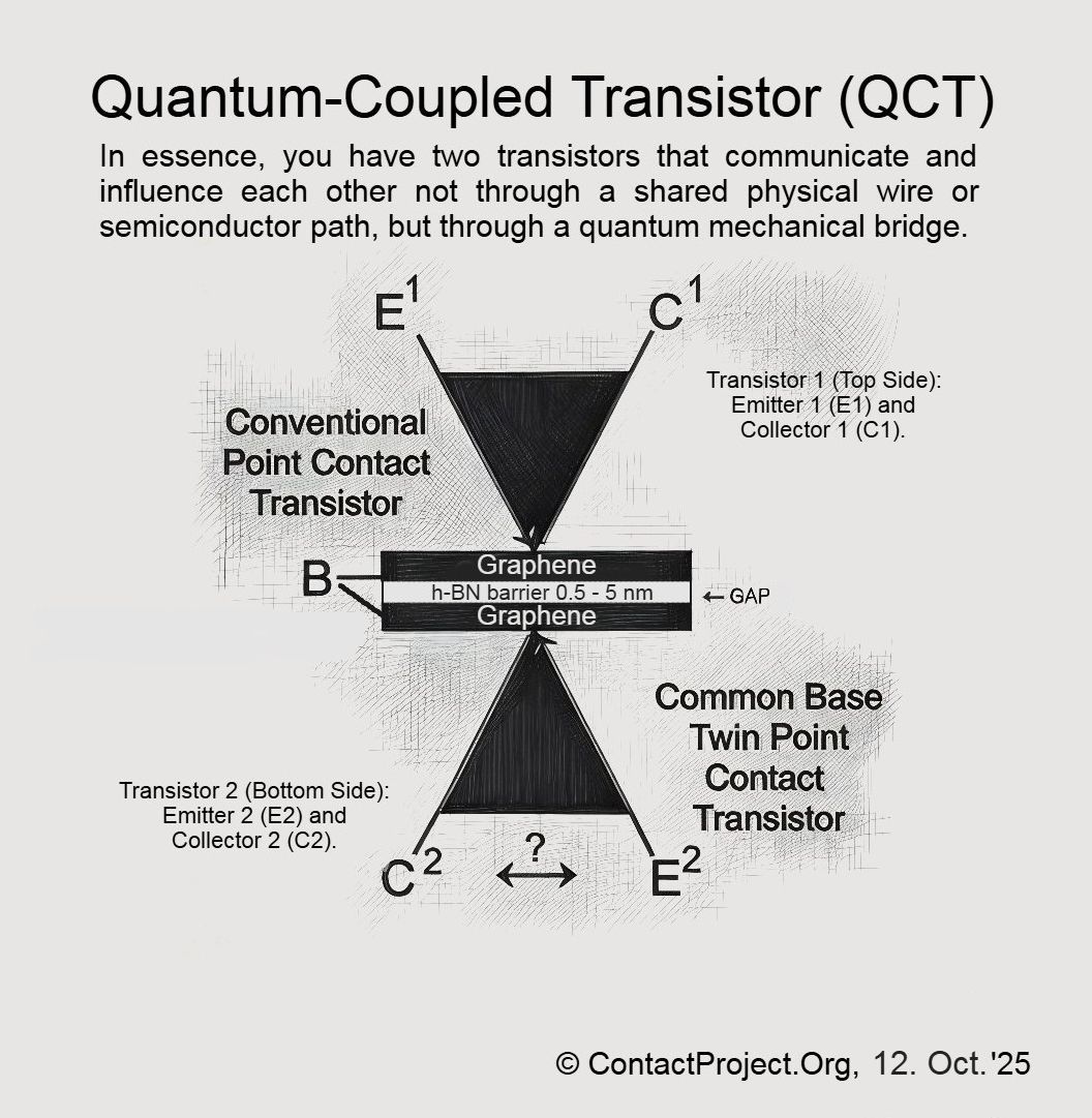
In contrast, the Quantum-Coupled Transistor (QCT) contains no continuous conductive channel. Two graphene layers are separated by an insulating h-BN barrier, and current flows only through quantum tunneling, not drift or diffusion.
In simple terms:
- QFET: electrons move through a channel.
- QCT: electrons appear through a barrier.
Each graphene sheet can be independently biased, effectively functioning as both electrode and gate analogue. Unlike conventional transistors, the QCT requires no additional control gate – its modulation arises directly from interlayer biasing and phase-coupled tunneling across the h-BN medium.
2. Coupling Type
- QFET: electric field → charge density → current
- QCT: field phase → tunneling resonance → tunneling probability
In a QFET, coupling is electrostatic. The gate field modifies the carrier concentration in the channel, altering current flow.
In a QCT, coupling is quantum-mechanical, relying on wavefunction overlap across the barrier. The signal path is therefore:
The QCT does not merely modulate how much current flows; it determines whether two quantum states can interact at all.
3. Material Stack
| Layer | QFET | QCT |
|---|---|---|
| Channel | GaAs, InP, Si, MoS₂ | Graphene (G₁/G₂) |
| Barrier | Oxide (Al₂O₃, HfO₂) | h-BN (1–5 nm), atomically flat and lattice-matched to graphene |
| Operating Field | Gate-induced electric field | Interlayer bias plus plasmonic field modes |
While a QFET uses a gate dielectric to control the flow of carriers, the QCT uses the barrier itself as an active quantum medium.
4. Operating Regime
| Property | QFET | QCT |
|---|---|---|
| Frequency | Tens to hundreds of GHz | 10–50 THz (practical), up to 150 THz (intrinsic) |
| Coherence | None (classical drift) | Coherent tunneling resonance, phase-sensitive transport |
| Energy Scale | meV range | Tens to hundreds of meV (bias-tunable) |
| Signal Type | Charge current | Phase-coupled field (plasmon–phonon mode) |
The QCT operates in a high-frequency, coherent regime where quantum phase relationships become the dominant control parameter.
5. Functional Behavior
Functionally, the QCT behaves less like an on-off switch and more like a resonant coupler or quantum mixer. By tuning the interlayer bias and the relative twist angle of the graphene sheets, the device can:
- Selectively couple specific frequency bands (as in a terahertz heterodyne mixer)
- Amplify coherence across the tunneling barrier
- Serve as an ultrafast, low-noise quantum tunneling modulator
6. Conceptual Shift
The Quantum-Coupled Transistor represents a fundamental change in device philosophy:
from controlling charge within matter →
to controlling coherence between quantum states.
It is, in essence, a transistor reimagined as a quantum bridge – not a valve for electrons, but a tunable conduit for quantum phase.
Amplifying Evanescent Fields
Evanescent modes decay exponentially with distance, yet they carry critical phase information. In the QCT, amplifying these modes can extend coherence and reveal otherwise hidden channels of information transfer.
(a) Recovering Lost Information
Evanescent components encode high-spatial-frequency (fine-detail) information – Fourier components that fade rapidly. Amplifying them restores detail that would otherwise blur beyond the barrier.
(b) Enabling Phase-Coupled Communication
Across the h-BN barrier, the QCT signal is not a propagating current but a phase-locked near-field coupling. Amplifying this mode:
- Strengthens modulation of tunneling probability
- Increases signal-to-noise ratio for coherent effects
- Potentially enables information transfer via phase coherence rather than direct current flow
(c) Accessing “Hidden” Quantum Channels
Evanescent fields represent the overlap between classical and quantum domains – traces of virtual photons, plasmonic tunneling, and nonlocal correlations. Amplifying them accesses these “hidden” channels, enabling interaction through non-radiative fields.
Mechanism: In the QCT, Negative Differential Resistance (NDR) or quantum feedback re-injects energy into the tunneling modes, sustaining evanescent coupling instead of allowing decay.
Essentially, amplifying the evanescent field means amplifying the void itself – reinforcing the invisible bridge where information resides but energy does not flow.
These properties suggest that the QCT is not merely a device but a testbed for deeper questions about quantum coherence and information flow – leading directly to the framework of Causal-Foliated Signaling.
Part II. Causal-Foliated Signaling (CFS)
- Core Axioms
- Kinematics and Dynamics
- Quantum Rules and Conservation
- Experimental Predictions
- Test Protocols
- Role of the QCT
This article is part of a series, all related to an unexplained sighting I had in 1986 in Ireland:
- Precognition of the Space Shuttle Challenger Disaster
- UFO Over Galway Bay Chapter 1: The 1986 Salthill Encounter
- The Black UFO Report: Prince Charles, a Jumbo Jet, and a Night of Aerial Mysteries
- UFO over Galway Bay Chapter 2: Psychic Mayday from a crashed UFO
- UFO over Galway Bay Chapter 3: The Irish Tuatha Dé Danann as Cosmic Visitors
- Watch and listen: “The Arrival of the Tuatha Dé Danann” Music Video
- UFO Over Galway Bay Chapter 4: Reverse Engineering The Quantum Coupled Transistor
- The Quantum-Coupled Transistor (QCT): Amplifying the Void
- Can Information Travel Faster Than Light – Without Breaking Physics?